Earlier this week I read an article on the Debian Weekly News, about a Debian box running on 3 Watts, and it reminded me of a project that I was asked to put on the shelf some time ago. The gist of the article linked to by the DWN was that Alex Perry got to wondering how much power his Linksys switch was sucking down whilst running 24/7, and found that his Manga, an ARM based router box, not only consumed less power but was able to run full blown Debian to boot. His point was "If I am going to pay to have a switch run 24/7, I might as well have the switch be a useful server as well." Following his article the PepLink community promptly got X11 working on the Manga and Alex's website was updated with the screen shots, which I might add are quite amusing.
While I do sympathize with the original thrust of the article, I must say that the Manga's ARM is a rather diminutive processor for a desktop machine these days. So my question is why would you run a Manga as a desktop to get down to the 3 Watt mark when for just a few more Watts you can run a box with a G4 processor? Yes, I am talking about that little machine that all of my geek friends (me included) seem to be drooling over as of late. The Mac Mini!
| The
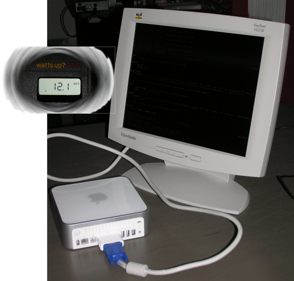
Mac Mini is a lot
of computer in a small footprint. The power reading was taken with a Watts up? Pro power meter with the machine idle running on the regular power supply (Not Batteries). (It is difficult to see the stuff on the monitor with the camera flash. If you look close enough you can tell that it is running.) |
 |
Several months ago I was in need of finding a small but powerful computer that could be run for a long period of time on batteries and not be a burden to carry. I was looking at several embedded options from places like Kontron and mini-box, when I saw an article on the Mac Mini. Looking at the limited specs for the Mac Mini on Apple's website I began to suspect that if I removed the cdrom drive I would be able to fit a "lithium-ion polymer" battery pack inside the vacated space. I say that I suspected this because Apple is lousy about posting specs about internals and stuff that your Grandparents wouldn't normally ask about. So I ran down to the local Apple store with my trusty calipers and had one of their technicians go into the back and measure the dimensions of the cdrom drive for me. The numbers that he gave me made my day, the batteries would fit! Now about power specs. Apple of course did not have the DC power specs online, and nobody I talked to at the Apple store or on the support line could get them for me. In an act of desperation I resorted to sending email to combinations of addresses like steve_at_apple.com sjobs_at_apple.com, steve.jobs_at_apple.com, etc asking for the specs. Funny enough I got a reply (No, not from Steve Jobs) from an Engineer who was quite helpful. It looked like the Mac could do it, so I decided to get one and hack on it. The Mac was dirt cheap compared to the embedded systems so it was a very limited risk approach to proceeding on the project.
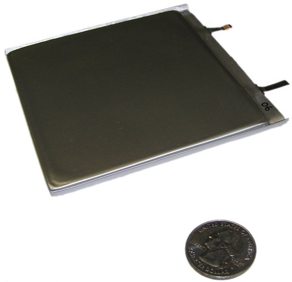 |
These Lithium-Ion
Polymer cells are rated at 4.2V
per cell maximum 3.6V average. Wait you haven't heard the best part... ...They are rated at 4Ah... ...and they are only $40 a piece. |
I ordered the Mac, a 4GB Hitachi Microdrive, and a laptop-IDE to CF adapter. I also talked to Mike (Dr. Zhang) at SKC PowerTech, Inc, and he was kind enough to send me some batteries for evaluation. The batteries were a new design and were not yet in production, so there was a bit of a lead time on those, but at the end of two days I had the rest of the necessities at hand. First things first, I measured the out of the box power draw of the Mac Mini, which turned out to be only 12 Watts! This was better than the specs I was given. I then proceeded to remove the hard disk and replace it with the Microdrive-CF adapter setup. Then I got me a Debian (Sarge) disk *GRIN*. This was the first time I had touched a Mac, and I was pleased to find that the Debian install on the Mac was smooth and painless. After getting the system up and running, I did some stress testing on it. The testing involved running simultaneous FFT routines (like 30 of them) on 80MB data files. The system was so heavily loaded that it took about 15 minutes to log into the machine from another terminal, and another 15 minutes to get to the bash prompt. During this utter thrashing of the system the highest the power usage spiked to was 20 Watts, but it stayed around 14 Watts most of the time. This was impressive...
This is where the bad news came... The batteries
came in, and not 30 minutes later I was informed that effective
immediately my time had been re-prioritized. Which is why
the
project had been put on the shelf. After reading Alex's article I just
had to make some time to hack on it, so a couple of nights ago I did
and I am pleased to report that the trial was a successs. This test was
only a feasibility test, and there is a lot of work left to do on the
system. For instance I still need to design the circuit protection for
the batteries. For now I have been trickle charging the battery pack
with a Topward power supply set to limit voltage and current to 20VDC
and 50mA. Ultimately I want to use this thing with a heads up display,
but for now I am using a monitor so it is not quite as portable as I
would like *GRIN*. Read on for
the Tech details of the test and pretty pictures...
| Materials | Source |
| 1 Mac Mini | Apple Computers |
| 1 4GB Microdrive | Hitachi |
| 1 IDE to CF adapter | mini-box.com |
| 5 Li-ion polymer cells | SKC PowerTech, Inc |
| Tools Needed |
| Putty Knife to open Mac |
| Small Phillips Screwdriver |
| Soldering Iron |
| An ESD workstation is recommended |
| Kapton Tape |
| Insulated Wire |
| Connectors are nice |
| Couldn't have done this with out my Fluke™ Multimeter |
Getting Started
Disclaimer: I am not
responsible for
anything you
do with the information you find on this site. If you are hacking
hardware to make it do stuff it was not intended to do you are most
likely voiding your warranty. Lithium-ion batteries can be quite
dangerous if not used and recharged correctly. If in doubt always
follow the advise of the manufacture and ignore the ramblings of crazy
geeks like me. This hack worked for me, but your mileage
may vary.
Now that we have the formalities out of the way,
the first thing that needed to be done was to open up the Mac,
and disassemble it so that the battery power leads could be soldered
onto
the motherboard.
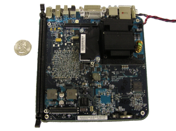
I placed the bare board on an ESD mat and plugged in
the power cable. Then with my multimeter I probed the voltages on each
pin on the power connector where it was soldered to the board. The
Power cable has 10 conductors in it, 6 of which are neutral conductors,
and 4 of which carry 18.66V DC. The neutral conductors are shorted
electrically to the conductor's shield and the chassis ground. The
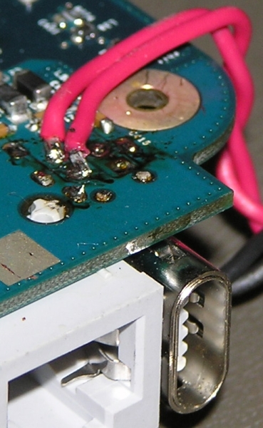
connector has 5 pins soldered to the motherboard, and 3 spots where the
shield is soldered to the motherboard. 2 of the pins (which have red
wires soldered to them in the pictures below) are 18.66V, two of the
pins are neutral, and the other pin is regulated inside the connector
to
1.33V (which is used presumably to power the on/off switch). According
to the Engineer at Apple, the Mac Mini should be able to operate
anywhere between 20VDC and 10VDC. Caveat: If you plan on using the
firewire port to power any external devices you cannot drop below
18.5VDC before those devices can start to suffer power loss.
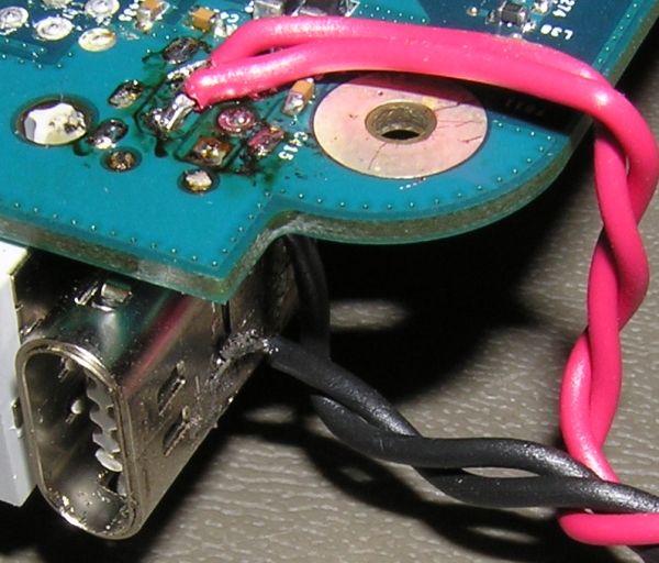 |
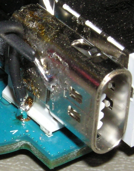
You will notice that I used 2 strands of wire for both the 0V and 18V
rails. I did this because I was using 24 Gauge wire to solder to the
board, and wanted to make sure that I had a fat enough current path to
the battery. I had to solder the 18V rails to the bottom of the
motherboard because there was no other place that was accessible. Of
the 0V rails I soldered one wire to the shield pin and the other to the
shield itself (See the pictures below). By the way, sorry about the solder flux, I ran out of Acetone. |
 |
 |
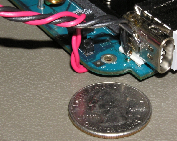
| Notice the twisted
quad coming off the board in the
picture to the right. It probably isn't necessary since the system is
going to
be
operating inside an RF shield (The Chassis), but it is neat and tidy,
and it is
better to be safe than sorry. |
 |
The Battery
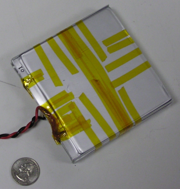 |
To get the 18V nominal
voltage that the system needs I
used 5 of the SKC PowerTech cells wired in
series which gave me a 4Ah 20V battery. Caveat: There is not much room to stuff these in the Mac Mini. So make sure you use Kapton tape or similar because electrical tape will make the battery pack too thick! WARNING: These cells do not have circuit protection on them. That means there is no electrical limitations on sourcing or charging current. SKC PowerTech sells an off the shelf 4-cell battery pack with circuit protection if you are not confident. |
Reassembly
| Now that the battery is built and the Mac is ready to accept the battery, it was time to put the system back together. Here are all of the parts: | 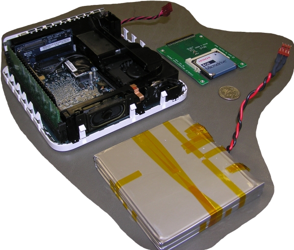 |
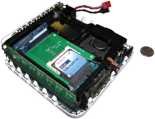 |
Putting the Microdrive
into the computer. This should be self explanatory. Notice the piece of foam under the Microdrive. The adapter card does not have horizontal mounting holes so the foam was necessary to stabilize the card. I am planning on replacing it with a 6GB Microdrive which has a direct 40pin IDE connector when they become available. |
| Now put the battery in. Look at that, a perfect fit! Isn't it pretty? | 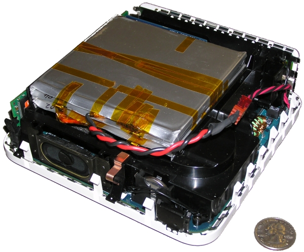 |
The Moment of Truth
Caveat: There are a couple things I should note here, fortunately they can be easily dealt with. I will update this page when I have the fix. First, remember back in the wiring section when I said that there was a 1.33V pin power connector soldered to the motherboard? When I first plugged the battery in I was assuming that that pin would be regulated off of the 18V line on the battery, but apparently it is isolated and there seems to be a regulator inside the connector itself. So when I plugged in the battery and pushed the power button, to my disappointment nothing happened. I got out my voltmeter and measured the voltage off the battery and the voltage going to the board and everything seemed to be correct, so I plugged in the power cable and hit the power button...
...The Mac started right up, so I pulled out the power cable...
...And it kept right on going.
The second thing I wanted to mention, and this is IMPORTANT, these cells don't have a circuit protection on them. So when you recharge them, do not use the Mac's power cord. Instead use a power supply which has voltage & current limiting knobs on it. Check the specs on the batteries for the current charge curve and stay within it. Don't blame me if you fry your Mac's power supply or burn down your house.
The Triumph
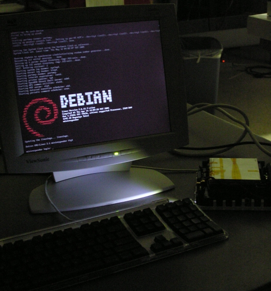 |
The Mac Mini... Running Debian... On Batteries... |
| I have got better things to do with my time than sit around and watch a computer screen!!! | 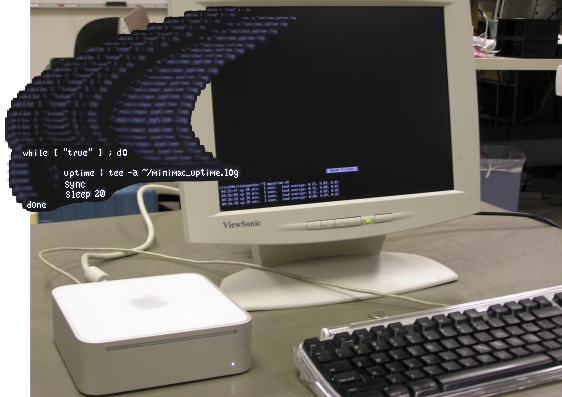 |
Conclusion
The Mac Mini ran, under very heavy
load, for just
over One Hour and 50 Minutes (1:50) on the Li-ion Polymer batteries!
TODO:
Design a circuit protection board (CPB).
CPB should include a 1.33V voltage regulator to run the power switch.
CPB should include voltage and current regulation so that the battery
can be charged from the
power cable.
Trickle charging is slow, so implementing "smarter" charging on the CPB
is a good idea.
Needs a battery monitor for power management.
Configure suspend/sleep states.
Configure Wake On LAN.

